
Product details
WARNING
1.Earthing:
*Please ensure that the power outlet socket is properly earthed for maximum safety.
*Explosion hazard. Do not ground to a gas supply line. (as shown the figure)
*Please make sure that the power outlet socket and plug are dry.
2.For safety, always disconnect the pump from the mains for repair or maintenance .
3.The pump is strictly prohibited from immersing into the water. The antifreeze shall be applied if water temperature is below 4°C.
4.Never move the water pump by pulling or holding the power cord as it will cause breakage and short circuit. Please carry the water pump with both hands.
5.The water pump is designed to pump clear water only that is free from explosive substances and solid particles or fibre. Never use the pump for pumping flammables and /or explosive liquid such as gasoline, alcohol, etc. as it will cause explosion.
6.Installation and maintenance must be carried out by qualified personnel . Improper repair may cause personal injury and damage to the equipment. In addition, the product warranty shall be void due to wrong application.
7.If the power cord is to be extended or replaced, use only the same or higher wire specification. Please make sure connection is secured, waterproofed and fully insulated.
8.The manufacturer will not assume any liability in case of any modification to the water pump.
9. DO NOT DRY RUN (WITHOUT WATER SUPPLY) !
1. INFORMATION ON THE PUMP
Thanks for using our pump. Please read this user manual before installation. Installation and operation must comply with local regulations and accepted codes of good practices. Children shall not handle the appliance. Cleaning and maintenance shall not be made by unauthorized personnel.
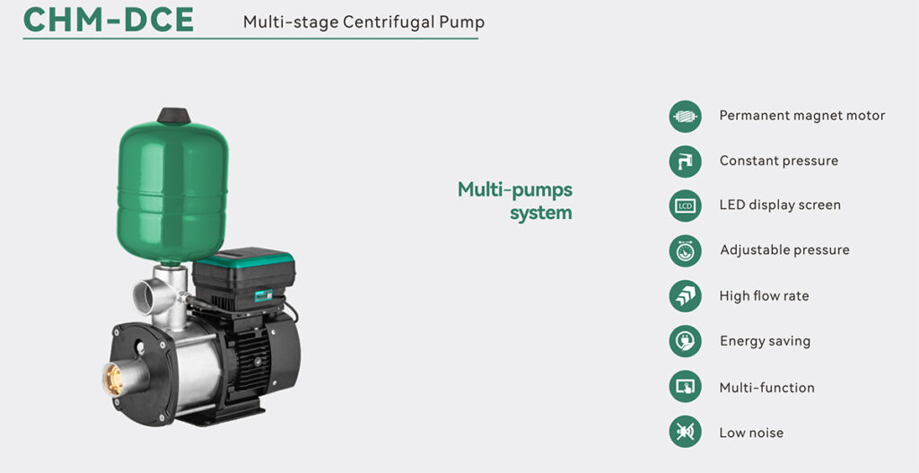
Intelligent inverter pump provides constant water pressure for a variety of domestic and light commercial applications. The booster pump consists of pump, permanent-magnet VFD motor, diaphragm tank, pressure sensor and intelligent controller. The intelligent controller is integrated with motor speed control, all-in-one pump control, fault protection, and display screen. It is easy to install and to operate.
You can set your desired requirement on the control panel of our intelligent inverter pump. The pump can supply constant water pressure so that the user is no longer bothered by water pressure fluctuation due to a rise or fall in demand, or from start / stop function. The variable speed motor will save energy and noise reduction. Please keep this manual after reading it along with warranty card as reference.
1. Performance
| MODEL | CHM8 -3DC | CHM12 -3DC | CHMT8 -3DC | CHMT12 -3DC |
| POWER | 2 .2kW | 2 .2kW | 2 .2kW | 2 .2kW |
| Volt / Hz | 220V 50Hz | 220V 50Hz | 380V 50Hz | 380V 50Hz |
| Motor Input Current | 8 .0A | 8 .0A | 5 .2A | 5 .2A |
| Rated Q. | 8 .0 m³/h | 12m³/h | 8 .0 m³/h | 12m³/h |
| Rated H. | 45m | 30m | 45m | 30m |
| Max. Q. | 13m³/h | 16m³/h | 13m³/h | 16m³/h |
| Max.H. | 55m | 55m | 55m | 55m |
| Speed | 4000r/min | 4000r/min | 4000r/min | 4000r/min |
| Section | 40mm | 50mm | 40mm | 50mm |
| Optimal Range | 1 . 5 – 5 .0 kgf/cm² | 1 . 5 – 5 .0 kgf/cm² | 1 . 5 – 5 .0 kgf/cm² | 1 . 5 – 5 .0 kgf/cm² |
1. Model
CHMT8-3DC
CHM-Series Number
T- Three phase
8- Rated Q.(m3/H)
3- Impeller Qty.
DC- Permanent magnet motor
WORKING CONDITIONS
PH Value: 5-8
Ambient Temperature : 0-40 °C
Ambient humidity : max. 85% (RH)
Liquid Temperature : 0-60 °C
(The maximum temperature of liquid shall not be over than 75 °C)
INSTALLATION DIMENSION

wirning diagram
Power wiring diagram
Single-phase Wiring Diagram
Wiring terminal:
U,V,W are 3-phase motor connection
E is ground wire connection
L, N are the interface of single-phase power supply

Pressure transmitter wiring diagram
2. Pressure transmitter wiring Diagram
1Mpa Voltage Type pressure transmitter is factory standard.
Current Type pressure transmitter is not available for this model

3. Pump sets Connection
1. The maximum is 5 pumps to connect for a unit.
2. Set different IP(1,2,3,4,5) for each pump by b08
3. If using by single pump, must set IP for 00 by b08.
4. All the power cord must connect with a same air switch/the same power supply. To avoid voltage difference to damage the controller.
5. Connections by signal lines.
6. Set a same pressure value for each pump of pump sets

Note: The wiring of the controller must be strictly in accordance with the requirements of this manual, otherwise the controller will be damaged! The internal connection of the controller has a text comment, please check it carefully.

7 APPLICATION
Pump water from well or main pipe
CHM-DC: Make sure the pump body and inlet pipe are completely fill with water from outlet when the outlet check valve is lifted.
CONTROLLER SETTING AND OPERATION
A. Press + and – together to unlock/lock the controller.
B. Press MODE to select the working mode: 1.BOOSTING, 2. TIME ( 0.5H, 3H,12H)
C. Press the + or – to set the working pressure of the pump. Then the pump can automatically work according to set pressure.
BOOSTING : To increase the water pressure upwards
Application: Domestic water supply, Pressure systems, Irrigation pumps
Working pressure factory settings : 2.8kgf/cm2
Calculate Working Pressure Value :
P– Working Pressure Value (Head)
H– The vertical height between the pump outlet and the highest point of use;
( 1.0kgf/cm2 ≈ 10m)
P=H/10+1.0kgf/cm2
TIMING: Filling in the tank according to selected time interval
Application: Pump water from ground tank/mains to roof tank by selected time interval.
Avoid start & stop frequently. (Automatic start by set time, stop when the ball float switch off as the tank is full.)
Working pressure factory settings : 2.8kgf/cm2
* The drainage outlet in roof tank must fit a ball float switch.
Calculation of Working Pressure Value:
P– Working Pressure Value (Pump Head)
H– The vertical height between the pump outlet and the highest point of use;
( 1.0kgf/cm2 ≈ 10m)
P=H/10+1.0kgf/cm2
8 CONTROLLER PANEL
Controller panel

| Button/ Indicator |
Function | |||||
| Display screen | ||||||
| A sequential fast showing of factory settings will be displayed. “Factory code (PLD)” > “Power” > Control board version number (such as u01) > Display board version number (such as U01) at the beginning when power is turn on. (e.g. :PLD > 0.75 > u01>U01). | ||||||
| 1. At automatic mode, the real-time pressure value is displayed. The values of other items can be switched to display by the “UNIT” button. | ||||||
| 2. At emergency mode, real-time motor speed is displayed. | ||||||
| 3. The setting item or parameter value is displayed during setup. | ||||||
| 4. Warning code is displayed when the pump or controller is faulty | ||||||
|
|
1. Switch on/off the pump manually. | |||||
| 2. Long press for continuous running of the pump. | ||||||
|
|
1. Lock/unlock the controller panel: press + and – together at the same time. | |||||
| 2. Set the working pressure: press + or – to adjust the working pressure value. | ||||||
| 3. Toggle setting items on setup menu. | ||||||
| 4. Adjust the digit | ||||||
|
|
1.Click to select working mode: | |||||
| Boosting and timing | ||||||
| 2.Press MODE for 3 seconds, all factory set parameters shall be restored. | ||||||
|
|
1. Enter setting menu. | |||||
| 2. Selection of the setting display on the screen. | ||||||
| 3. Save setting parameters. | ||||||
|
|
Press it to binding the APP and pumps through WIFI | |||||
|
|
Toggles the display item. | |||||
| m: pressure value in meter | ||||||
| r/min: motor speed | ||||||
| kw: motor power | ||||||
| kgf/cm2: pressure value in kgf/cm2 | ||||||
|
|
Press it to enter manual mode, then set the motor speed by button “-” or “+” and press on/off button to start the pumps manually. | |||||
| The pump must be stopped manually for energency working mode. | ||||||
|
|
The indicator of boosting working mode | |||||
|
|
The indicator of timing working mode | |||||
| Select the mode Timing. Then make selection on time interval. | ||||||
|
|
Selection of time interval for Timing | |||||
| Light off : Timing mode is turned off. | ||||||
| Automotically pump water to roof tank from well or ground according to selected time interval. | ||||||
| RUN: | ||||||
|
|
Light permanently on: Pump is running and the pressure is same as the set working pressure value; | |||||
| Light flashing on: Pump is running but the pressure lower than the set working pressure value; | ||||||
| Light off : Pump is not running. | ||||||
|
|
DRY RUN (Lack of water supply) | |||||
| Light on means the pump stopped with no water supply. | ||||||
| When you have eliminated the fault or the fault disappears | ||||||
| by itself, the light will be turned off automatically. | ||||||
|
|
Power indicator | |||||
| Light on indicates the power is on. | ||||||
| Light off indicates the power is off. | ||||||
|
|
Multi-pump mode (maximum 5 pumps to connect together is allowed). | |||||
| Light off: single pump mode or multi-pump mode but without communication signal. | ||||||
| Light permanently on means the pump is mater pump in multi-pump system. | ||||||
| Light flashing on means the pump is slave pump in multi-pump system. | ||||||
|
|
Indicate the working mode of emergency . | |||||
|
|
Light permanently on: successfully connected WIFI. | |||||
| Light quickly flashing on: the pump is binding APP. | ||||||
| Light slowly flashing on: no connected WIFI. | ||||||
| Light off: it is not included Wifi module or the Wifi module is failed. | ||||||
|
|
Light on means the panel is locked and the buttons cannot be used. | |||||
| Press “+” and “-” at the same time to lock/unlock | ||||||
| The panel will automatically lock when it is not operated for 5 minutes. | ||||||
|
|
b01 [Range : 10-90%, FS:80%] | |||||||||||||||||
| Set the start pressure value. | ||||||||||||||||||
| The pump will be automatically started at the percentage below the working pressure value. | ||||||||||||||||||
| E.g.: the pressure setting is 2bar, the start pressure is 2barx80%=1.6bar. | ||||||||||||||||||
| Navigation: Press “SET” > “b01” > “SET” > Adjust digit [10~90] > “SET” to save or wait for 20s it will be saved automatically | ||||||||||||||||||
| 泵的启动工作压力与泵设定工作压力的百分比可设定 (设置范围在10 -90%之间) , 按加减键一 次数值变化1; 出厂设定值为80; | ||||||||||||||||||
| B02 : [00 : Positive 01 : Reverse, FS:00] | ||||||||||||||||||
| Adjust motor rotating direction. This parameter setting must stop the motor to adjust. | ||||||||||||||||||
| Positive rotation for WZB and LDB-Z series are clockwise when view from fan cover side. | ||||||||||||||||||
| Positive rotation for CHM and LDB-M series are counterclockwise when view from fan cover side. | ||||||||||||||||||
| Navigation: Press “SET” > “ + ” or “ – ” > “b03” > “SET” > Adjust digit [ 0 ~ start pressure] > “SET” to save or wait for 20s it will be saved automatically | ||||||||||||||||||
|
|
b03 : [Range: 0-Start pressure, FS:0.5 bar] | |||||||||||||||||
| Water shortage protection value, if the working pressure falls lower than the set value, pump will stop functioning. | ||||||||||||||||||
| After shortage protection, the pump will start at interval of 1H,2H,4H,8H. | ||||||||||||||||||
| The pump will start immediately when the main pipe restore water supply. | ||||||||||||||||||
| Navigation: Press “SET” > “ + ” or “ – ” > “b03” > “SET” > Adjust digit [ 0 ~ start pressure] > “SET” to save or wait for 20s it will be saved automatically | ||||||||||||||||||
| 管 路 缺 水 判 定 的 压 力 值 可 设 定 ,按 加减键 一 次 数 值 变 化 为0 . 05kg f/c m², 出 厂 设 定 值 为0 . 5 kgf/cm²;设置值为0时 ,缺水判定功能失效 (注:持续缺水 ,缺水后重 启时间分别为1小时、2小时、4小时、8小时; 自来水管道来水立即重启) ; | ||||||||||||||||||
| b04 : [Range:10-180 second, FS:180] | ||||||||||||||||||
| The time taken for pump to stop working when it is dry run. | ||||||||||||||||||
| Navigation: Press “SET” > “ + ” or “ – ” > “b04” > “SET” > Adjust digit [10 ~ 180] > “SET” to save or wait for 20s it will be saved automatically | ||||||||||||||||||
| 缺水判定时间值可设定(设定范围为10 – 180秒可调), 按加减键一 次数值变化1秒, 出厂设定值为180秒; | ||||||||||||||||||
|
|
b05 : [00 : ON 01: OFF FS :00] | |||||||||||||||||
| Open or close the automatic protection function when the pump working pressure has erratic fluctuation. | ||||||||||||||||||
| Navigation: Press “SET” > “ + ” or “ – ” > “b05” > “SET” > Adjust digit [00 or 01] > “SET” to save or wait for 20s it will be saved automatically | ||||||||||||||||||
| 00–通过压力波动判断缺水有效 ,01–取消压力波动大判定缺水 , 出厂设定值为00; | ||||||||||||||||||
|
|
b06 : [ 00 : Pressure (Bar) 01 : Head (Meter), 02 :Motor Speed(RPM) ,03:Water Temperature(℃) ,04: Power (kw), FS:00 ] | |||||||||||||||||
| Set the real-time displaying item. | ||||||||||||||||||
| Navigation: Press “SET” > “ + ” or “ – ” > “b06” > “SET” > Adjust digit [00 ~ 04] > “SET” to save or wait for 20s it will be saved automatically | ||||||||||||||||||
| 00–管路实时压力 ,01–实时扬程 (单位:m) 02–实时转速 (单位:r/min) , 03–实时水温 (单位:℃) ,04–实时功率 ,显示为Px.xx (单位:kW) ; | ||||||||||||||||||
|
|
b07 : [Range : 10-50, FS:30] | |||||||||||||||||
| This setting should be reduced when the water outlet of the pump is closed and not easy to stop, and increased when the pump is stopped by mistake during operation. | ||||||||||||||||||
| Navigation: Press “SET” >“ + ” or “ – ” > “b07” > “SET” > Adjust digit [10 ~ 50] > “SET” to save or wait for 20s it will be saved automatically | ||||||||||||||||||
| 当电泵出水端关闭不易停机时, 需减小该设置值; 当电泵运行过程中出现误判停 机时, 需增大该设置值 ,调节范围10 – 50, 出厂设定值为30。 | ||||||||||||||||||
|
|
B14 : [00 : OFF 01: ON FS :01] | |||||||||||||||||
| Switch the function of anti-freeze protection. | ||||||||||||||||||
| Navigation: Press “SET” > “ + ” or “ – ” > “b14” > “SET” > Adjust digit [00 or 01] > “SET” to save or wait for 20s it will be saved automatically | ||||||||||||||||||
| 防冻功能开启/停用 。00 –停用 ,01 –开启 ,出厂设定值为01; | ||||||||||||||||||
| B15:[Range: -10 ℃ ~ +10 ℃ FS: 5 ℃ ] | ||||||||||||||||||
| To set the starting temperature of anti-freezing protection. | ||||||||||||||||||
| The pump will automatically start when the water temperature in pump body drop to this setting value and stop when the temperature up to B16 setting.Prevent the water in pump from freezing to broken pump body. It is based B14 setting Enable (“00”) | ||||||||||||||||||
| Navigation: Press “SET” > “ + ” or “ – ” ” > “b15” > “SET” > Adjust digit [-10 ~ 15] > “SET” to save or wait for 20s it will be saved automatically | ||||||||||||||||||
| 低水温电泵运转控制参数, 防冻功能开启时可以修改 ,调节范围为- 10℃至10℃ , 出厂默认值为5℃ ,当水温低于该值时 ,①电泵在保压待机或手动停机情况下强制 启动以1800r/min转速持续运转 ,直至泵腔温度达到b1 6 ( 20℃至40℃) 设置的阀 值 ,泵转为停机状态 。②电泵在“泵工作状态”情况下 ,维持“泵工作状态”不变。 | ||||||||||||||||||
|
|
B16:[Range: +20 ℃ ~ +40 ℃ FS: +30 ℃ ] | |||||||||||||||||
| Set the stop temperature of anti-freezing protection. | ||||||||||||||||||
| When the pump is started due to the activation of anti-freezing protection. It will automatically stop when the water temperature is up to this setting value. It is based B14 setting Enable (“00”) | ||||||||||||||||||
| Navigation: Press “SET” > “ + ” or “ – ” > “b16” > “SET” > Adjust digit [20 ~ 40] > “SET” to save or wait for 20s it will be saved automatically | ||||||||||||||||||
| 电泵停机温度参数 ,防冻功能开启时可以修改 ,调节范围为20℃至40℃ ,出厂默认 值为30℃ ,当水温达到该值时 ,泵转为停机状态; | ||||||||||||||||||
| B17 [Range: 40℃ ~ 130 ℃ FS: 75 ℃ ] | ||||||||||||||||||
| Setting the protection of water temperature. | ||||||||||||||||||
| When the water temperature exceeds this setting, the pump will stop for protection.After protection, the pump will automatically start when the water temperature is dropped 2℃ from the protection temperature. | ||||||||||||||||||
| Navigation: Press “SET” > “ + ” or “ – ” > “b17” > “SET” > Adjust digit [40 ~ 130] > “SET” to save or wait for 20s it will be saved automatically | ||||||||||||||||||
| 泵腔保护温度值 ,调节范围【 40 , 130】 ,默认75℃; 当泵腔温度超过此设定值时, 停机; 当泵腔温度比该设定值小2℃时, 电泵恢复运行。 | ||||||||||||||||||
7、 Working pressure setting
| NO. | Model | Factory Setting |
| 1 | CHM(T)8 -3DC | 2 .8 kgf/cm² |
| 2 | CHM(T) 12 -3DC | 2 .8 kgf/cm² |
Calculation of Working Pressure Value:
P– Working Pressure Value (Pump Head)
H– The vertical height between the pump outlet and the highest point of use; ( 1.0kgf/cm² ≈ 10m)
P=H/10+1.0kgf/cm2
PRECAUTIONS
“1. Whenever possible, install the water pump in shady, cool and dry area. If the water pump is to be used in the open area, don’t expose it to direct sunlight. Otherwise it will cause damage to the water pump and cause electrical hazard.”
“2. When used in shady area, it is recommended to install Y Type filter onto the suction pipe to prevent the sand from entering the pump body.”
“3. In winter freezing areas, make sure to turn on the anti-freeze function and keep the pump connected to the power supply. Do not cover the fan cover and heat sink of the motor with insulation material, which will cause poor ventilation and heat dissipation and cause a fire. When the pump is out of use, the water in the pump should be drained.”
4. When there is a heating system in the water supply line, it will produce a certain amount of water vapor, which may affect the use of the pump, it is recommended to install a pressure relief valve.
OPERATION AND MAINTENANCE
“1. Before starting the water pump, ensure that the power cord is properly connected, the voltage is correct, and all suction pipe and discharge pipe are well connected and sealed.”
“2. The relevant technical data of the water pump are indicated on the nameplate for reference.”
“4. If the pump is not used for long time, disconnect the power supply, drain the water and clean the pump body, store the water pump in shady, cool and dry area. When restart, if the water pump can’t operate normally, remove the fan cover and turn the fan manually until the fan can rotate smoothly”
“5. After 2000 hours of normal use, the pump should be maintained.”
“6. Rust-proof function: If the pump is in the power-on state and the pump has not been used for a long time, it will automatically run for 30 seconds every 24 hours to avoid pump body rust jamming the impeller.”
COMMON FAULTS AND TROUBLE SHOOTING METHODS
| NO. | PROBLEM | PROBABLE CAUSES | PROBABLE REMEDIES | |||
| 1 | The pump does not start | The pipe pressure higher | Increases working pressure | |||
| than pump’s setting value | value or adjust b01 parameter | |||||
| b01 parameter value too low | Increases b01 parameter value | |||||
| The pipe or tap is blocked | Check the pipe and tap | |||||
| 2 | The pump does not stop | Pressure sensor faulty | Change pressure sensor | |||
| Pipe leakage or tap is not fully closed | Check the pipe and taps | |||||
| Working pressure value is set too high | Decreases the working pressure value | |||||
| Motor reversal | Adjust the direction of motor rotation through B02 or adjust the wiring. | |||||
| The pipe is dry run but the dry run protection is not available. | Adjust the parameter of B03 or B05 to activate the dry run protection function | |||||
| 3 | The pump function but no water flows out | Motor reversal | Adjust the direction of motor rotation through B02 or adjust the wiring. | |||
| Pipe blocked or check valve does not open | Check the pipe and check valve | |||||
| No water supply | Awaiting water supply | |||||
| Error | Check the Error code on display | |||||
| 4 | The pump function but water flows is small | Motor reversal | Adjust the direction of motor rotation through B02 or adjust the wiring. | |||
| Air into pump body | Open the outlet of pump and keep running. | |||||
| The pipe of outlet is bigger than inlet. | Change the pipe | |||||
| The pipe of inlet is too small | Change the pipe | |||||
| NO. | WARNING CODE | REASON OF FAULT | SOLUTION | ||
| 1 | E01 | [Low voltage] | 1. The voltage rises to 180V (1phase) / | ||
| Input Voltage lower than | 310V (3phase), the fault will be | ||||
| 130V(1Phase) /245V(3Phase) | removed automatically and pump | ||||
| can operate again. | |||||
| 2. Install a voltage stabilizer. | |||||
| 2 | E02 | [Over voltage] | 1. The voltage drops to 280V(1phase)/465V (3phase),the fault will be removed automatically and | ||
| Input voltage higher than | pump can operate again. | ||||
| 280V(1Phase) /465V(3Phase) | 2. Install a voltage stabilizer. | ||||
| 3 | E03 | [Pressure sensor fault] | 1. Turn off the power, re-plug the signal wire to pressure sensor to ensure it is in good connection. | ||
| 2. Check the connecting terminal in controller and ensure it is in good | |||||
| connection. | |||||
| 3. Change to a new signal wire. | |||||
| 4. Change to a new pressure sensor. | |||||
| 4 | E04 | [IPM temperature too high] | 1. To cool the IPM module internal temperature to 80 degrees and below The pump will return to normal operation. | ||
| 2. Install the pump in well ventilated place. | |||||
| 8 | E08 | [Lack phase/Over current] | 1. Renew impeller or clear the rust and sewage. | ||
| a. Rotor locked as impeller is broken, blocked with pump body due to rust or sewerage | 2. Check or replace the connecting wire between motor and controller. | ||||
| b. Pool wiring connection between motor and controller. | 3. Change motor. | ||||
| c. The three-phase | |||||
| resistance of the pump is unbalanced due to the wading of the motor. | |||||
| d. The motor lack-phase. | |||||
| 9 | E09 | [IPM current too high and overloaded] | 1. Check and remove the case of overloaded motor. | ||
| 1. Overloading | 2. External environment interference. | ||||
| 2. Electromagnetic interference | 3. Check and replace the connection between motor and controller | ||||
| 3. Pool wiring connection between motor and controller. | 4.Replace the controller | ||||
| 4. IPM broken | |||||
| 10 | ERR | [Fault of pressure transmitter] | 1. Check and replace the wiring | ||
| 2. Replace the transmitter | |||||
| 11 | P01 | [Water shortage warning] | 1. Set the parameter of b05 to 01. | ||
| 1. The pump working pressure has erratic fluctuation. | 2. Reduce the b03 setting value or limited outlet flow. | ||||
| 2. Pressure lower than b03 setting. | 3. Replace small diameter pipe or add throttle valves | ||||
| 3. Outlet too big to keep pressure. | 4. Waiting water restore supply. | ||||
| 4. Water shortage | |||||
SPECIAL NOTE
1.The pump will be automatically protected and shut down when the pipeline is shortage of water during the operation. When the water supply is restored , it will restart and continue to work automatically.
2.The controller is used to pressurize the tap water pipeline. When the pipeline pressure is higher than the starting pressure of the pump, pump does not start. When the pipeline pressure is less than the pump starting pressure, the pump starts to work.


